
Outdoor CATV Line Amplifiers: Gain, Slope and 127dBuV Explained
A CATV line amplifier restores the level that coaxial trunk cable loses over distance, and it must do so without adding distortion. Gain sets how much level is restored, output capability sets how many channels can be carried before compression, and slope compensation matches the amplifier's response to the cable's frequency-dependent loss. A 127 dBuV output rating is only useful when it is quoted with a channel load and a distortion figure, because both determine the usable level.
What the three controls actually do
Gain is the straightforward one: it restores level lost in the preceding cable span. Slope, or tilt, compensates for the fact that coaxial cable loses more at high frequency than at low, so a flat amplifier output becomes a tilted signal at the far end of the span unless the amplifier deliberately tilts in the opposite direction. The third control is the sub-band split, which decides where the return path begins and how much low-frequency noise reaches the forward amplifier.
A fourth setting is often overlooked: the pad or equaliser at the input. An amplifier fed with a signal far above its design input will run its first stage in compression no matter how the gain is set, and the cure is attenuation before the gain stage, not less gain after it. Installers who reduce gain to cure distortion are reducing the output while leaving the input stage overloaded, which is why the picture improves slightly and then fails again at the next channel change.
These three interact. Raising gain to recover a long span also raises the level at the amplifier output, which pushes the output stage closer to compression. Tilting the response to compensate cable loss changes the level of the highest channels, which are usually the first to suffer when the stage runs out of headroom.
Why gain flatness matters more than the gain figure
An amplifier that delivers 34 dB at 50 MHz and 28 dB at 860 MHz has a 6 dB tilt built in. If the specification does not say so, the installer discovers it at commissioning, when the low channels are over-driven and the high channels are marginal. Flatness within about 1 dB across the working band means the gain figure applies to every channel, which is what a level budget assumes.
This is also why a 34 dB amplifier is not automatically better than a 26 dB one. The useful question is what the response looks like at the frequency where the system is weakest, not what the maximum gain is at the frequency where it is easiest to achieve.
What 127 dBuV actually buys
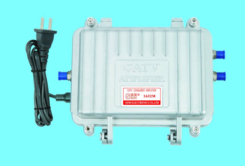
Output capability determines how many channels can share the amplifier before intermodulation products rise into the picture. A trunk carrying 40 analogue-equivalent channels needs more headroom than one carrying 12 digital multiplexes, because the composite power is higher and the distortion products accumulate. The 1632 publishes 127 dBuV output with a noise figure of 7 dB or better, which is a working figure for a trunk segment rather than a laboratory maximum.
| Parameter | 1632 published value | What it decides |
|---|---|---|
| Gain | 26 / 30 / 34 dB selectable | How long a span can be recovered in one stage |
| Output level | 127 dBuV | How many channels can share the amplifier |
| Noise figure | 7 dB or better | The noise floor contributed at the head of the span |
| Sub-band split | 42 / 54 / 65 / 85 MHz selectable | Where the return path starts and how much ingress enters the forward path |
| Powering | AC 60 V through the trunk | How many amplifiers one power inserter can feed |
AC 60 V powering along a trunk
Outdoor amplifiers are usually powered through the coaxial trunk rather than from a local mains supply, because a mast or a street cabinet rarely has power. AC 60 V is fed from a power inserter at the head end and passes through each amplifier to the next, with each unit drawing a small current. The practical limits are the current capacity of the inserter and the voltage drop along the cable, which is why the number of amplifiers per inserter is a calculation rather than a rule.
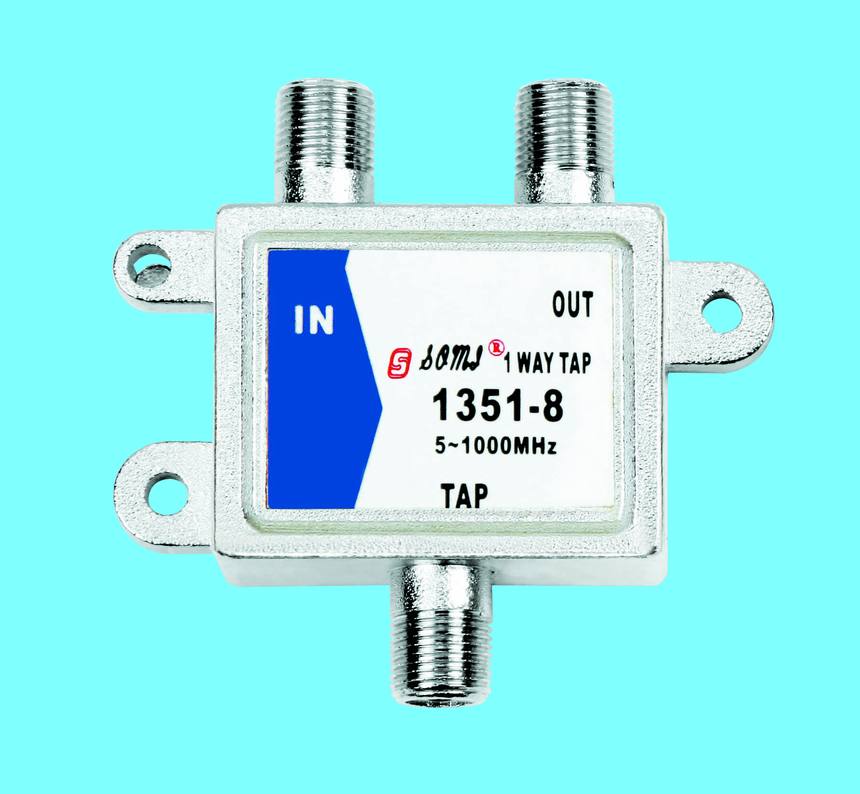
Two details decide whether the chain works. The first is that every unit in the chain must pass power, including splitters and taps that sit between amplifiers. The second is that the DC path must be broken where the trunk leaves the powered section, otherwise the inserter feeds an unintended branch and the voltage sags everywhere.
A worked selection example
Consider a trunk segment fed by a 1632 outdoor line amplifier, 300 metres of RG11 at 860 MHz, with 40 dB of loss at the top of the band and 22 dB at 50 MHz. The tilt across the band is therefore 18 dB, and a flat amplifier cannot compensate for it without over-driving the low channels. A 34 dB gain setting recovers the level at the top of the band, and the amplifier's slope or the cable equaliser absorbs the rest. The output level after the stage must stay below 127 dBuV with the full channel load, and the input level must stay above the point where the 7 dB noise figure dominates.
Commissioning checks that catch a bad design
A trunk that measures correctly at the head end can still fail at the last tap. The checks below are the ones that separate a commissioned system from a connected one.
- Measure level at both ends of every span, at the lowest and highest channel, and record the tilt.
- Confirm the output level at each amplifier with the full channel load, not with a test carrier.
- Verify power voltage at the last amplifier in the chain, not just at the inserter.
- Check that unused tap ports are terminated.
- Record the gain and split settings on each unit so the next visit does not start from zero.
Need this checked against your own signal chain?
Send the cable schedule, channel load and span lengths and we will return gain, split and powering settings for each stage. Send the details through our inquiry form or reach the team on the contact page.
Request a quotation